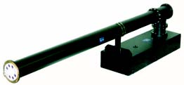
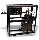
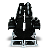
MCi offers broadcast frequency and channel combiners in star-point, constant impedance, manifold, and other high power configurations. Micro Communications manufactures waveguide and coaxial frequency / channel combiners to combine two or more channels into a common antenna.
MCi is an Emmy ® award winner for Adjacent Channel Combining Technology for the broadcast industry. Recently, we built a set of special 5-channel combiners for the United States Navy. Please explore the common designs of MCi broadcast frequency and channel combiners below.
Broadcast Star-Point Combiners
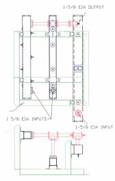
MCI’s Star Point Combiners are used to combine two or more channels into a common antenna. Up to five channels can be combined using this approach. The Star Point Combiner consists of interdigital bandpass filters constructed of a number of tuned cavities. The amount of cavities is based on the frequencies to be combined. The filters are combined into a common “T” using properly phased coax lengths. This design of combiner is ideal where the power levels are of relatively low to medium power. MCI also manufactures the broadband antenna systems that compliment these combining networks.

Specifications & Design Features
- Low Cost
- Low Loss
- High Isolation
- Low VSWR
- Compact Size
| VSWR: | 1.30 (each channel) |
| Frequency: | Specify channels |
| Insertion Loss: | 0.6 dB (each channel) |
| Isolation: | 30 dB (between inputs) |
| Cooling: | None Required |
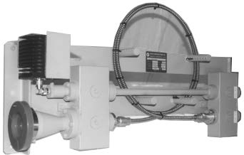
High-Power Waveguide UHF-TV Dual Channel Combiner
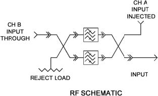
The MCI dual channel UHF-TV combiner is a constant impedance device consisting of two waveguide bandpass filters and two hybrids. The combiner allows two high power UHF-TV transmitters, operating on different channels, to use a common feedline and antenna system without causing interference to each other.

It offers low insertion loss and VSWR on both channels. A typical design provides 35dB minimum isolation with a 6 section bandpass filter for a single channel separation. Reducing the number of filter sections for large spaced channels would result in somewhat decreased through channel insertion loss. The maximum channel separation is determined by the waveguide size and for optimum performance should not exceed a 30% frequency bandwidth. Final specifications are dependent on the frequencies to be combined.
Design & Specifications
- All Waveguide
- Small Volume
- High Power
- High Isolation
- Low Insertion Loss
| Frequency: | Specify Channel (14-70) |
| VSWR: | 1.10 Both Channels |
| Insertion Loss: | 0.25 dB Through Channels 0.1 dB Injected Channels |
| Isolation: | 35 dB Both Channels |
| Power: | 140 kW Model #: 41229, 41228, 41227 280 kW Model #: 41219, 41218, 41217 |
Coaxial Constant Impedance Channel Combiners
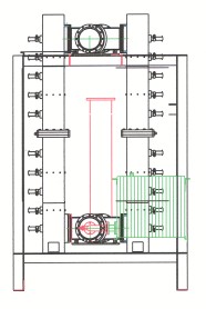
The MCI Channel Combiner is used where it is necessary to combine two or more channels to a common antenna. New channels can be added by connecting another channel combiner in tandem to the previous. The limitations of the number of channels to be combined are the power handling and the bandwidth of the antenna system used. The combiner is a constant impedance type with bandpass filters acting as a through filter for one channel and a band stop filter for the other channel. The filters provide low loss and high isolation. MCI also manufactures the broadband antenna systems that compliment these combining networks. Additional filtering for the wideband input available on request.

Design Features & Specifications
- Constant Impedance Design
- High Isolation
- Low Loss
- Low VSWR
- Compact Size
- High Power Handling
UHF Broadcast Manifold Multi Channel / Frequency Combiners
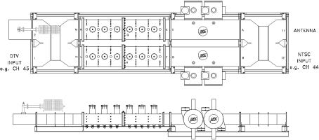
Micro Communications, Inc. offers a full range of UHF channel combiners in star-point or (manifold) configurations. The channels are combined into one antenna feed line. The number of cavities in any of these combiners is determined by the spacing between the channels within the system. Typically, for most requirements, four bandpass cavities per channel will suffice with a channel spacing of 24 MHz or more.
The cavities are designed and constructed to ensure good stability over a wide range of environmental changes. A variety of layouts are available with overall sizes depending on power levels, number of channels to be combined and other considerations. Construction is usually from rugged aluminum welded flanged cavities within a freestanding aluminum frame.
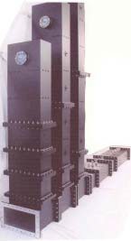
MCI bandpass filters, as always, are precision tuned at the factory to provide optimal reflective and transmissive phase matching, ensuring good in-band VSWR while minimizing insertion losses. In systems where the channel spacings are less than 24MHz, the use of six section bandpass filters are incorporated. Thermally stable filter designs are also available.
Design Features & Specifications
- Silver Plated Iris for Optimum Performance
- Inductive Iris Design for High-Power
- Wide Passband for Each Channel or Center Frequency
- Input with VSWR Tuner
- Low Insertion Loss
Resources: Other Broadcast Frequency & Channel Combiner Products
MCi: A Microwave Techniques Company
To learn more about MCi Broadcast Frequency and Channel Combiners, please contact us at [email protected] – we look forward to hearing from you, and partnering on your next broadcast, RF or microwave project!
